Arduino Programming
- jjinghui21
- Dec 3, 2022
- 3 min read
Hello lads welcome to my blog *+.^!
There are 4 tasks that will be explained in this page:
1. Input devices:
a. Interface a potentiometer analog input to maker UNO board and measure/show its signal in serial monitor Arduino IDE.
b. Interface a LDR to maker UNO board and measure/show its signal in serial monitor Arduino IDE
2. Output devices:
a. Interface 3 LEDs (Red, Yellow, Green) to maker UNO board and program it to perform something (fade or flash etc)
b. Include the pushbutton on the MakerUno board to start/stop part 2.a. above
For each of the tasks, I will describe:
1. The program/code that I have used and explanation of the code. The code is in writable format (not an image).
2. The sources/references that I used to write the code/program.
3. The problems I encountered and how I fixed them.
4. The evidence that the code/program worked in the form of video of the executed program/code.
Finally, I will describe:
5. My Learning reflection on the overall Arduino programming activities.
Input devices:
Interface a potentiometer analog input to maker UNO board and measure/show its signal in serial monitor Arduino IDE
Code/program in writeable format | Explanation of the code |
int sensorPin = A0;
int ledPin = 13;
int sensorValue = 0;
void setup()
{
pinMode(ledPin,OUTPUT);
}
void loop()
{
sensorValue = analogRead(sensorPin);
digitalWrite(ledPin, HIGH);
delay(sensorValue);
digitalWrite(ledPin, LOW);
delay(sensorValue);
}
|
|
Below are the problems I have encountered and how I fixed them.
By right, the LED should light up when it is dark. But for me, my LED turned off when it is dark despite me copying the code from the maker uno guide. I didn't fix this issue as it still function like how an LDR would.
Another problem I had was when I covered the LDR with my bare fingers, it did not turn off. So, I had to use the sleeves of my sweater as it was opaquer.
Below is the short video as the evidence that the code/program work.
Interface a LDR to maker UNO board and measure/show its signal in serial monitor Arduino IDE
Code/program in writeable format | Explanation of the code |
int LDR = A0;
int ledPin = 13;
int LDRvalue = 0;
void setup()
{
pinMode(ledPin,OUTPUT);
}
void loop()
{
LDRvalue = analogRead(LDR);
if(LDRvalue > 600)
digitalWrite(ledPin, HIGH);
else
digitalWrite(ledPin, LOW);
}
|
|
Below are the problems I have encountered and how I fixed them.
I did not know why my LED did not light up despite having assembled it according to the picture in the maker uno guide. Then I compared it to the picture, and I realised I used the other side of the bread board. I thought that the red line was on the outside for both sides therefore the orientation did not matter.

Below is the short video as the evidence that the code/program work.
Output devices:
Interface 3 LEDs (Red, Yellow, Green) to maker UNO board and program it to perform something (fade or flash etc)
Code/program in writeable format | Explanation of the code |
const int greenLedVehicle = 5; const int yellowLedVehicle = 6; const int redLedVehicle = 7; void setup() { pinMode(greenLedVehicle, OUTPUT); pinMode(yellowLedVehicle, OUTPUT); pinMode(redLedVehicle, OUTPUT); } void loop() { { digitalWrite(greenLedVehicle, LOW); delay(2000); digitalWrite(yellowLedVehicle, HIGH); delay(2000); digitalWrite(yellowLedVehicle, LOW); digitalWrite(redLedVehicle, HIGH); delay(1000); digitalWrite(redLedVehicle, LOW); digitalWrite(greenLedVehicle, HIGH); delay(2000); } } |
|
Below are the problems I have encountered and how I fixed them.

Unlike the previous 2 activities where there was an example I could copy off of in the maker uno guide. For this activity's code, I had to tweak one of the examples in the maker uno guide. To the left is the original code provided. it had 5 LEDs instead of 3 and had a push button included already. Therefore, I had to simplify the code in order to meet the criteria of the activity.
Changing the code was slightly challenging as I had gotten a few error messages while trying to delete some codes.
Below is the short video as the evidence that the code/program work.
Include pushbutton to start/stop the previous task
Code/program in writeable format | Explanation of the code |
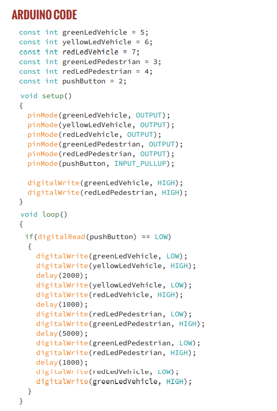
const int greenLedVehicle = 5; const int yellowLedVehicle = 6; const int redLedVehicle = 7; const int pushButton = 2; void setup() { pinMode(pushButton, INPUT_PULLUP); pinMode(greenLedVehicle, OUTPUT); pinMode(yellowLedVehicle, OUTPUT); pinMode(redLedVehicle, OUTPUT); } void loop() { if(digitalRead(pushButton) == LOW) { digitalWrite(greenLedVehicle, LOW); delay(2000); digitalWrite(yellowLedVehicle, HIGH); delay(2000); digitalWrite(yellowLedVehicle, LOW); digitalWrite(redLedVehicle, HIGH); delay(1000); digitalWrite(redLedVehicle, LOW); digitalWrite(greenLedVehicle, HIGH); delay(2000); } } | The blue highlighted parts are added the the previous code in order to include a push button. Therefore i shall only explain the blue parts.
|
Below are the problems I have encountered and how I fixed them
I didnt really encounter much problems for this activity since it was the last one.
Below is the short video as the evidence that the code/program work.
Below are the hyperlink to the sources/references that I used to write the code/program for all the activities:
Learning Reflection on the overall Arduino Programming activities.
Arduino is not that difficult as I had expected. When faced with a long string of code, it is indeed overwhelming however, after breaking it down and understanding what the words mean, it is not so bad. This doesn't mean that the often occurrence of error messages popping up after verification still don't irks me. It has become one of my biggest pet peeves now.

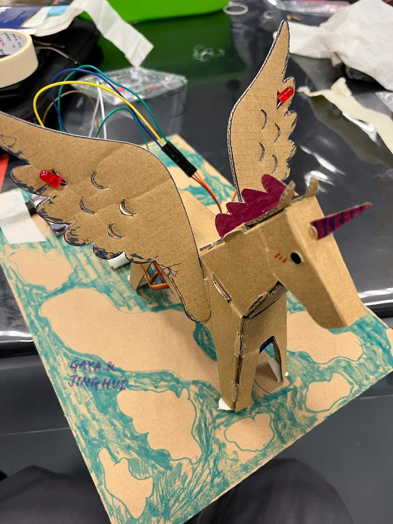
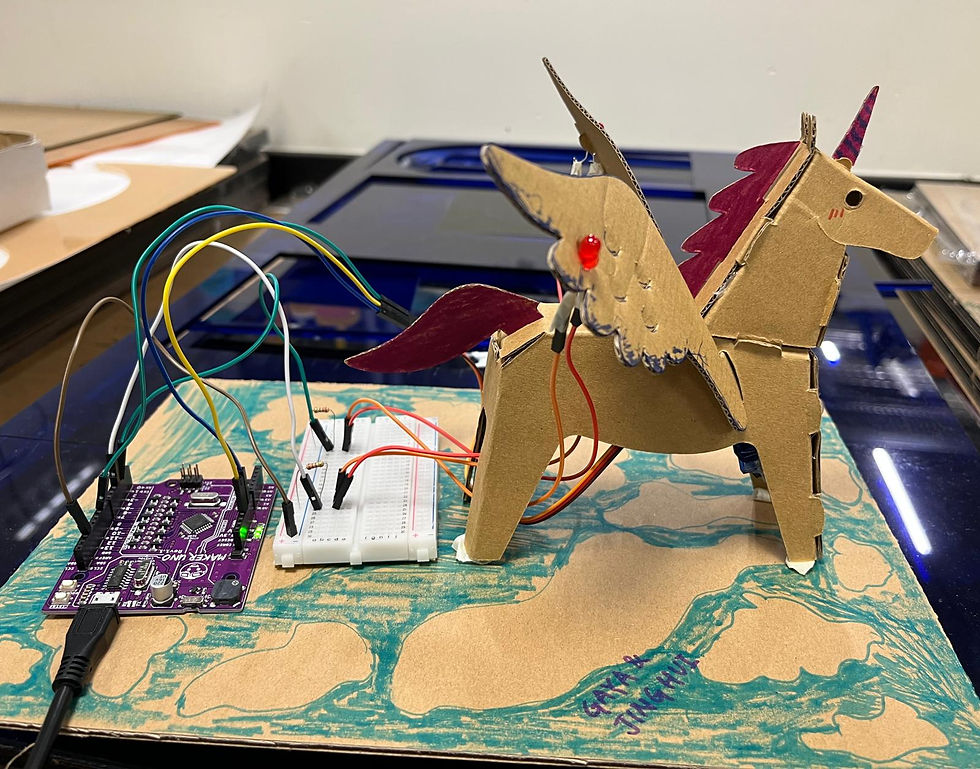
The practical activity was fun. I got to team up with Gayathri to make a pegasus. I felt that we did a great job as we got to add other functions and colored the pegasus. We added music and 2 red LEDs, one on each wings. Both LEDs light up at the same time together to the beat of the music. I felt that we could have made the lights alternating instead so that it could be actual turn signals. But that is too ambitious for a time limit of 2 hours.

However, we did run into a crisis towards the end of the practical, our servo motor was slightly out of place which made our wings flap quite weakly. We were panicking and trying our best to hot glue it a back. But this time we had all the other wirings in the way >:((
Video of our pegasus :))))


Comments